
Directional drill setup
Show entry area, locating equipment, utility controls and protected work zone.
LOWER-SURFACE-DISTURBANCE OPTION
A directional drilling system advances underground loop paths from compact entry and exit areas. It can cross beneath established surfaces while reducing continuous trenching.
GOOD STARTING FIT
Sites where surface disruption matters and a qualified directional-drilling contractor can establish safe bore paths, setbacks and locating control.
Horizontal directional bore is included in this site’s preliminary WaterFurnace PremiumPath screen. Final program eligibility still depends on qualifying equipment, engineering, property, credit, documentation and current PremiumPath/Palmetto rules.
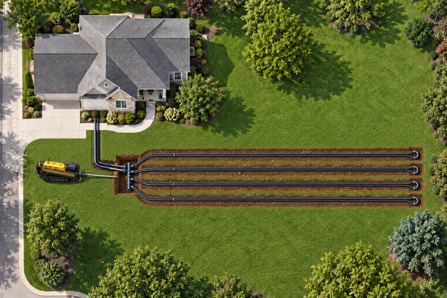
A simplified, not-to-scale overhead view: two header lines run from the home to a manifold pit shown approximately 25 feet into the lawn, feeding four straight conceptual bore circuits shown 15 feet apart. The boring machine is positioned in the grass on the driveway side, and one connected U-bend for each loop emerges at the far side. Actual bore path, depth, spacing, circuiting and capacity require site-specific engineering.
INSTALLATION SEQUENCE
The team maps utilities, structures, grades and the planned bore profile, including entry angle, depth and separation.
A steerable pilot bore is tracked underground, enlarged when required, and used to pull the specified geothermal pipe into place.
Circuits and headers are connected, pressure-tested, flushed and recorded on the final as-built plan.
PROS
TRADEOFFS
FIELD DOCUMENTATION
A useful project record shows the parts of the loop installation that affect access, performance, restoration and future service. These are the field views we document for this loop type.
Show entry area, locating equipment, utility controls and protected work zone.
Document pipe handling, bend radius, connections and surface protection.
Pair the concealed routing with measured as-built depths and finished surfaces.
SITE VERIFICATION
FROM SCREENING TO SITE DESIGN